BCI + Electronics
The Hardware
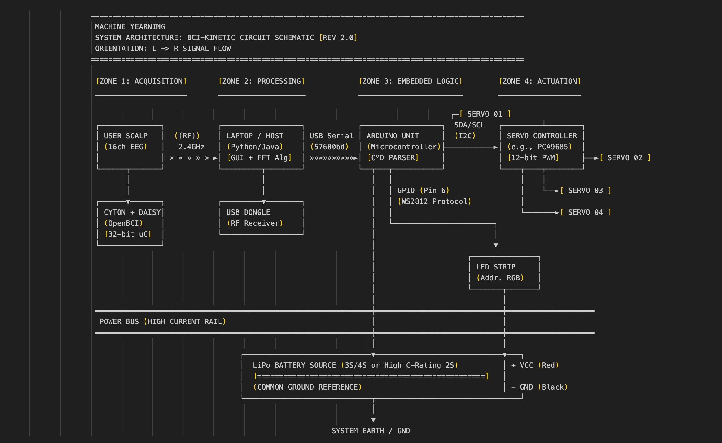
I used the 16-Channel EEG Ultracortex headset from OpenBCI, equipped with Ag-AgCl dry comb electrodes. The headset is powered by the Cyton-Daisy boards. The electrodes were evenly distributed across the head, in accordance with the 10-20 system. Although the electrodes can (and often should) be concentrated to specific areas of the brain for targeted data, I found an even distribution sufficient.
Signal Processing
An important part of the BCI set-up is feature extraction. As I explain later, I was able to extract one feature from my brain—just one binary that I could actually control on command.
This was achieved with decent hardware and basic software. I would have loved to train a model on a dataset of thousands of Motor Imagery EEG data for more precise control, as well as to reduce environmental noise and motion artifacts with modifications such as active electrodes. Unfortunately, this was slightly out of the scope of this project.
The EEG data collected by the Ultracortex is transmitted via Bluetooth to a laptop, which processes the data and outputs it in two ways.
The Visual Output
This allows users to examine the data in various data types, such as FFT plots, band power bars, time series, polarity, spectrograms, and more of various fidelity and processing. The GUI also allows users to interact with the data by adjusting filters, toggling specific channels, and checking impedance.
For Machine Yearning, this is not a strict requirement. The data does not *need* to be visualized in the GUI for the project to function; the processing can just happen internally. But I choose to display it in my Keynote presentation and in exhibitions/galleries because viewers—whether new to neurotech or experienced in it—find it fascinating and love to talk about it.
The Control Output
The second output is critical for Machine Yearning to function. An important part of the processing is aggregating the frequencies of the data collected by all 16 channels into a single value between 0 and 1, which measures the “concentration level” of the user.
This single value is measured against a pre-set threshold (for me, the threshold was usually 0.8, but it varies with different people and different environments). When the value is above the threshold, it signals a “concentration.”
The Handshake
This signal is sent serially to an Arduino Uno worn by the user. (In theory, this could be WiFi or Bluetooth, but I ran into issues with Arduino connectivity and latency during testing).
An important note at this stage is that a laptop is technically not required. If the GUI is forgone, the computing power required to process the data decreases significantly. It becomes feasible to process the data on a Raspberry Pi (or similar) and connect that to an Arduino—or even consolidate the Arduino into the Pi potentially. This would greatly reduce the quantity of hardware required to run Machine Yearning and simplify the design.
Actuation
The Arduino is pre-programmed with the desired controls for the servo motors and the LED strip.
I programmed each servo with specific range limits to prevent over-extension. Programming the desired movement—the specific curls, rotation, and lighting—felt more like choreography than engineering.
Once the “concentration” signal is sent to the Arduino, the Arduino kicks off the choreography. The servo controls are transmitted via a servo controller and the LED strip has precise RGB diode control. There is a large battery powering the servos, while the laptop sends power to the Arduino and LED.
All in all: whenever the user concentrates, the limbs move.
The specs of the servos and battery are not finalized—there can still be some testing done here. Most of my iterations with the electronics were with the power supply. Of course, this is linked with the industrial design of the limbs as well. For example, lighter limbs can work with weaker motors, which means the battery can be smaller.
Fabrication + Industrial Design
Here, we dive into the design process of the limbs, as well as the fabrication methods and the iteration required to achieve them.
Core Tenets
The first core tenet is that both limbs are intentionally non-humanoid, an idea I justify in *The Design Philosophy*. Although I sourced many mechanical references from humanoid robot assemblies, I had to get creative and resourceful in the design.
The second core tenet is that both limbs are accessible to build. This means relatively low-cost digital fabrication, low-cost materials, and a repairable, modular design. There are no factory-machined parts, and there is no glue in the entire assembly. I will justify this further when I talk about myStudio.


The Tentacle Limb
The basic design is adapted from tentacle special effects and props for movies. Most famously, the chestburster from *Alien* was a tentacle puppet inside, controlled by a puppeteer offscreen. Many other tentacles, trunks, and snakes from Hollywood are controlled by a similar system.
Mechanism
The fundamental mechanism is a flexible core tube with vertebrae running along it.
When a wire is pulled at the base, the entire tentacle curls in that direction. To adapt this mechanism for Machine Yearning, I designed a wearable, motorized, pulley system. There are 4 wires, but they are in opposing pairs, so only 2 pulleys are required, and as such, only 2 motors.


Iteration
Initially, I oriented the mechanism in a + shape, with one pair of wires going up and down and the second pair of wires going left to right.
In testing, I realized that this led to a lot of weight and strain on the top wire, since it was effectively pulling up the entire limb against gravity. I designed two solutions to this problem:
1. Re-orientation: I re-oriented the wires into an X shape. Now, 2 motors drive the upwards curl movement. This did require some translation in the motor programming to ensure that both are actuated simultaneously.
2. Reinforcement: I added a second steel wire to the top 2 pulleys, so that there was less strain on each wire to prevent fraying and crimp failure. However, both wires needed to be exactly the same length for this to work properly.


Vertebrae
The vertebrae needed to attach to the core without rotating, spinning, or sliding. This was more challenging than anticipated. It was not possible to have a perfect tolerance fit, since the core was a bit soft and did not have an even diameter all the way along.
I tried melting heat-set inserts into the PLA vertebrae and using set screws to pressure fit the parts in place. This worked temporarily, until the screws started to scratch and scrape out the rubber of the core and the part got loose.
The next step was to just screw the vertebrae into place by driving a hole directly into the core. I did this in my latest iteration, after I was confident in the length of the core, the number and spacing of vertebrae, and the design of parts. I didn’t want to make changes after making a bunch of holes in the core. A more editable design for this is probably warranted.
Note: The vertebra that receives close to all of the load is the one at the very tip. It provides the resistance on the front end, with the pulleys providing resistance on the back end. Everything else in between just guides the mechanism to move like a tentacle. It is important that these parts are especially strong (e.g., higher infill in the front vertebrae, a second screw securing it to the core, and securing the pulley to the motor which is secured to the mount).


Mount & Welding
After building a proof of concept of the tentacle mechanism, I designed a shoulder/back mount so that it could be worn.
Design priorities for the mount included structural integrity, repairability, comfort, and cable management. The mount houses the 2 motors, the pulley wheels attached to the motors, and the base of the tentacle itself. The base attaches to an ergonomic mesh backplate with backpack straps. This results in an ergonomic weight on the user; since the limbs push the user’s center of gravity slightly further out in front, the backpack straps prevent imbalances and provide support. The mount is securely screwed into the mesh.
There are 2 slots for servo motors facing upwards, such that both pulleys are horizontal. In early prototypes, I had one pulley horizontal and one pulley vertical, but this took up too much space coming up off the user's shoulder.
Spinning motors and pulleys with steel wire right next to the user’s head is already a little uncomfortable, so I needed the pulleys to be as close to the body as possible and out of the line of sight.
Now, I have one pulley horizontal and the other pulley tilting downwards on the back of the user, following the downward slope of the shoulder. This meant that I needed to guide the wires from the mouths of the pulleys into the specific holes in the base vertebrae. To do this, I designed antennae coming up from the mount in front of each pulley to feed the wire in-line with the pulley. These had to be strong to actually turn the wire, but still lightweight, minimal to be unobtrusive to the mechanism, and 3D-printable.
This meant that the layer lines had to be perpendicular to the forces applied on the antenna and also the rest of the mount itself for strength.
The Welding Technique:
I printed the mount in thirds, with each section aligned optimally. I cut in dovetail joints on each part for a mechanical adhesion. Then, I used a 3D printing pen to essentially weld the gaps of the parts together.
At first, this was clumpy and unsightly, but I got the hang of it after practicing. Although not quite as strong as a solid piece (since the weld is only on the outside of the joint), this technique still resulted in stronger and cleaner parts than other methods like JB Weld, superglue, or screws.
Also, I designed precise cable management channels for the servo wires, so that they could exit at the back of the user and have access to the servo controller board.
A note on adhesives:
In very early prototypes, I used hot glue to quickly adhere servo motors to a PLA mount. After just a few seconds of run time, the servo motors would heat up just enough to slightly melt the hot glue, completely delaminating the joint! Pretty much immediately the servo motor would just be flailing around. This is one of several reasons why I refused to use any glue or adhesive in later designs. In later versions, I just screwed the servo into the mount.

The Jointed Limb
With the jointed limb, there were some very specific augmentations I wanted to explore.
1. Extended Range of Motion: Longer than your biological arms. It reminds me of the toy extension claws. In my research and interviews, this is one of the first things that comes to people’s minds when asked to think about upgrading their body.
2. Bioluminescence: This may be a deprecated idea ever since the invention of the lightbulb, but I think it’s an incredibly fascinating feature of certain creatures that I’ve always wished humans had. This is why the jointed limb also glows and changes color (one of many ways to design light into objects, as opposed to like color traces from Tron, or more utilitarian things like a flashlight).

The Mount
As opposed to the tentacle limb mount which only had one attachment point to the mesh back, the jointed limb mount has two. This is for added lateral stability.
The point of the jointed limb is to have an extended range of motion further away from the body, resulting in a further center of gravity. As the limb articulates, the center of gravity moves with it, swaying the user back and forth, forcing them to counteract. This also results in the mount eventually slipping and sliding off the shoulder and shearing off the mesh. To reinforce this, I just added a second point of attachment.

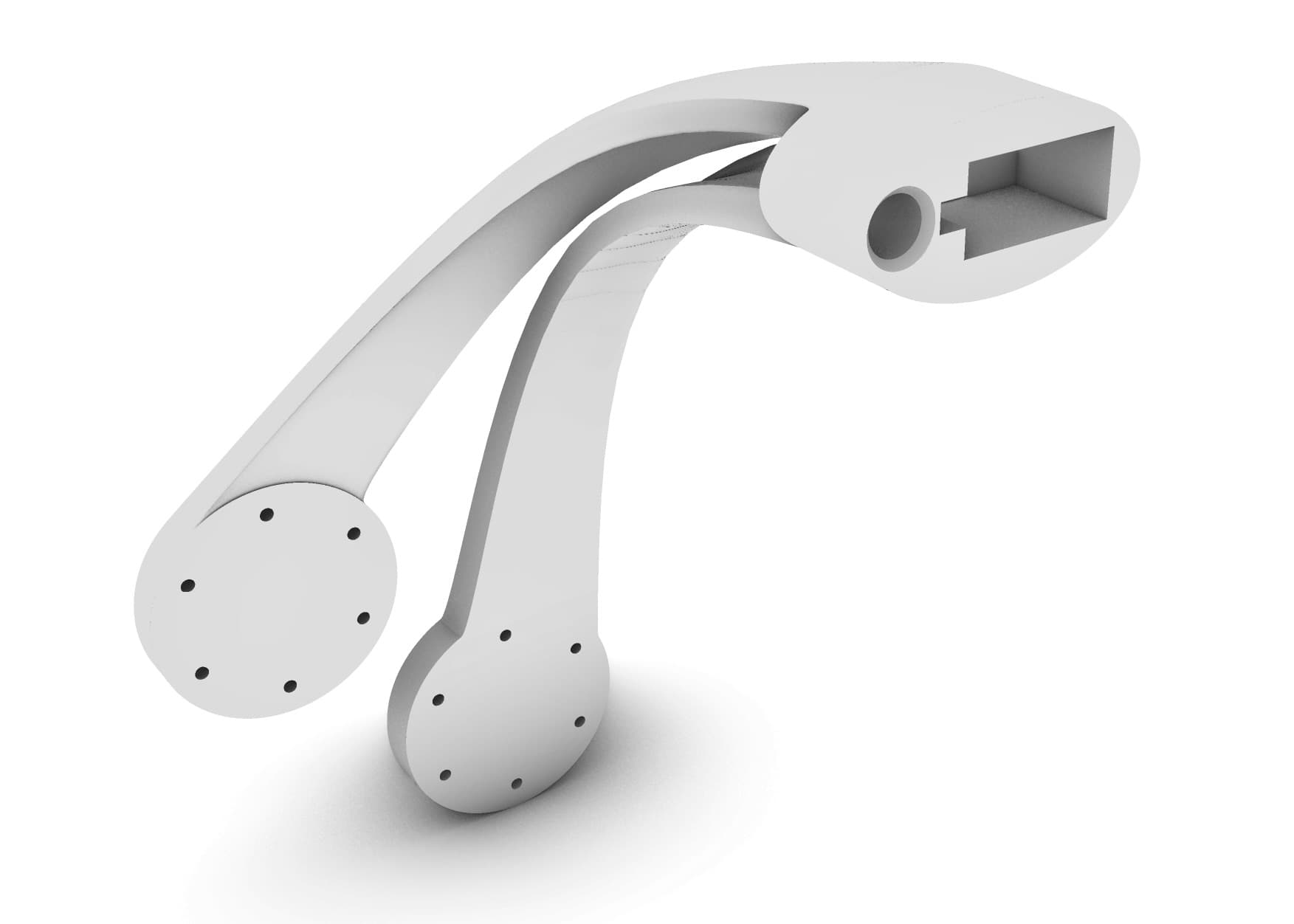
Skeleton & Construction
Both stages of the limb have essentially the same construction. The skeleton is a single aluminum beam running through each one.
Both aluminum beams are slotted into custom PLA parts on each end.
The Schematic:
There is a motor in the shoulder mount facing front, with the upper limb attached to it at about a 30-degree angle. At the tip of the upper limb is the PLA part which contains the second motor and the lower limb is attached to this, but parallel to the upper limb.


Cable Management
An LED strip runs along the entire length of the limb, attached to the aluminum beams. It exits at the mount, plugging into the Arduino.
A design challenge here was cable management. At each hinge, there is an LED strip and servo motor cables that cannot be rotated because they will just get twisted up. The limbs have to rotate, but the wires within them cannot. To solve this, I created cutouts in the PLA parts within the range of the jointed limb’s rotation.
This way, the wires essentially stay stationary while the limb is articulating.
To cover all of this, I used translucent PLA. I experimented with various degrees of infill for an optimal frosted effect to diffuse the light from the LED. In retrospect, I would have liked to explore further the silhouette of the limb and play around with more shapes rather than just a tapering cone. At the time, I was concerned about durability but I realized that the PLA is more structurally sound than I thought, even at that size.